1 functional requirements
Design a voice-activated LED lantern, which can be applied to the background decorative light source of wall, window, exhibition hall and various handicrafts. It can control the color and pattern of the lantern through AT89C51 single-chip control, which has a good decorative effect. At the same time, the lighting can be switched to the white light illumination mode by sound, and the illumination mode duration can be adjusted as required.
2 Scheme design and selection
2.1 LED color control design
According to the principle of three primary colors of color synthesis, light of any color can be synthesized according to different proportions by changing the three primary colors of red, green and blue. When mixed with red, blue and green light, yellow light can be obtained separately. , cyan and magenta; when the three colors are mixed in equal proportions, white light can be obtained; and when the three colors are mixed in different proportions, light of different colors can be obtained. The principle of controlling the color of the LED by the single-chip microcomputer is to give different duty ratios of the three primary colors.
In order to achieve different colors. The color formula is: R[x%]+G[y%]+B[z%]=C.
For example: R[100%]+G[0%]+B[100%]=magenta; R[100%]+G[100%]+B[0%]=yellow; R[0%]+G [100%]+B[100%]=cyan; R[100%]+G[100%]+B[100%]=white
2.2 Choice of plan
According to the requirements of the function, the design is divided into three modules, the control module with AT89S52 single chip as the core, the sound control circuit module and the LED backlight display module.
3 hardware circuit design
3.1 single chip system and LED display circuit
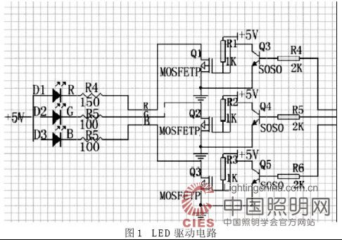
LED background light display circuit is composed of 3 three-in-one full-color LED chips in parallel. The chip has 4 pins, the common terminal is directly connected to the 5V voltage regulator, and the red light source cathode pin is connected in series with 150Ω resistor and single-chip microcomputer P1. The 0 pin is connected; the green light source negative pin is connected in series with the 100Ω resistor and the P1.1 pin of the single chip; the blue light source negative pin is connected in series with the 100Ω resistor and the P1.2 pin of the single chip. The drive circuit is shown in Figure 1 and Figure 2.


3.2 voice control circuit
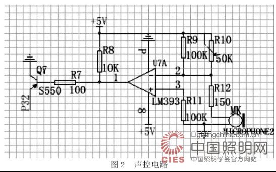
MK converts sound signals into voltage signals. R10 is a 50kΩ variable resistor that is used to adjust the sensitivity of the voice control. The LM393 is a low power, low offset voltage dual comparator that can be directly connected to TTL and CMOS. It is used as a low frequency operational amplifier. R8 is a 10kΩ pull-up resistor to ensure that the output level is low and the output of the LM393 is connected. The base of the PNP transistor, the collector of the triode is grounded, and the emitter is connected to the external interrupt P3.2 pin of the MCU. When the MK has a sound signal transmission, the P3.2 pin will be low.
4 software program design
The design is to control the color change of the full-color LED and the change of brightness by controlling the duty ratio of the P1.0, P1.1 and P1.2 pins by the AT89S52 microcontroller. The main program part is mainly used to realize the color change of full-color LED and the pattern. When P3.2 appears low level, an external interrupt occurs. The interrupt mode is active low. The interrupt program is used to realize the illumination mode of white light. The duration of the mode can be set by interrupting the program in the program, which is generally set between 40s and 60s.
5 Conclusion
This paper designs a voice-activated lantern, the control chip uses AT89S52 single-chip microcomputer, and details the principle of LED color change, the principle of sound control and the design of hardware and software. The sensitivity of the voice control can be achieved by adjusting the varistor in the circuit. In general, the applause within 5 meters can trigger the circuit to run. The sound-controlled lanterns are mainly based on decoration and lighting, and the lighting is only an auxiliary function, so the time control under the lighting mode should be grasped.
Fpc Ffc Connectors,Car Charging Connector,Industrial Ethernet Connector,Automotive High Current Connectors
Zooke Connectors Co., Ltd. , https://www.zookeconnector.com
