1 System description
A car tire pressure monitoring sensor is installed inside each wheel, which can accurately measure the pressure and temperature inside the tire. The sensor sends the tire pressure value and temperature to the body controller (BCM) according to a certain rule through wireless form Value, BCM sends the information frame to the instrument panel through the CAN bus, and the driver obtains the pressure value and temperature value of each tire through the instrument panel display. When the pressure value or temperature value of a certain tire exceeds the alarm value, the instrument panel can accurately display the location of the alarm tire, and emit graphics, sound, and text alarms. At the same time, the low-frequency antenna installed at each tire fender position communicates with the BCM, and parses and converts the operation information required by the BCM car tire pressure monitoring sensor into 125 kHz low-frequency wireless data, and the car tire pressure monitoring sensor Will receive this low-frequency wireless signal, and then work according to the parsed operation information. The above is the TPMS two-way communication system. Since this product is a safety part of automobile products, it should have high reliability in various environments. The various environments are: under various weather conditions, such as cloudy weather, rain, and other different weather environments; various road conditions, such as national roads, High speed, country roads, mountain roads, etc .; snowy roads, ice surfaces, extremely cold areas in winter (-40 ℃); hot and humid areas in summer (surface temperature +50 ℃, 90% humidity); different speeds ( 0 ~ 200 km / h) etc. This requires strict selection of various devices when designing automotive tire pressure monitoring sensors.
2 Circuit design
Since the car tire pressure monitoring sensor is installed inside the tire and does not contact the outside world, this requires that it cannot be repaired and repaired too frequently. Generally, it requires a working life of 10 years, and its operating temperature range is -40 ~ +125 ℃, which It is required that the devices selected should be automotive-grade and low-power components.

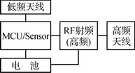
Figure 1 Block diagram of the system
The block diagram of automobile tire pressure monitoring sensor system is shown in Figure 1.
2.1 Sensor selection
MCU / Sensor is the core of the system and is realized by SP300V2.1E1060 of Infineon. SP300V2.1E1060 integrates silicon micromachining pressure sensor, temperature sensor and acceleration sensor and a battery voltage monitor, and internally integrates a low-power 8-bit Harvard RISC controller; it has power-off, operation, idle , Shut down 4 kinds of working modes, and there are 3 kinds of wake-up modes such as IT / LT wake-up, PORT wake-up and LF low-frequency detection wake-up, which can effectively meet the system low-power design requirements. Pressure measurement range 0 ~ 3.5 Bar; temperature measurement range -40 ~ + 125 ℃; centripetal acceleration measurement range -12g ~ 115g; working voltage range 1.8 ~ 3.6 V.
2.2 RF unit selection
RF radio frequency chips are mainly used to convert digital signals into high-frequency signals. The system uses Maxim's MAX7044 chip, its operating voltage is + 2.1 ~ +6.0 V, low operating current of 8 mA, OOK / ASK modulation, communication rate can reach 100 kbps, small package 3 mm & TImes; 3 mm, 8 pins SOT23 package. It eliminates the problem of SAW-based transmitter design; adopts a crystal structure to provide a greater modulation depth and fast frequency response mechanism; reduces the effect of temperature, the temperature range can reach -40 ~ +125 ℃. It contains power amplifier (PA), crystal oscillator (crystal oscillator), driver (driver), data effective detection circuit (data acTIvity detector), lock detection circuit (lock detect), phase-locked loop (32x PLL), frequency division Circuit (frequency divider 16) and other circuits.
The MAX7044 has an automatic low power mode (shutdown mode) control method. If the DATA pin is inactive for a certain period of time (wait time), the device automatically enters low-power mode. The waiting time is about 216 clock cycles, and the frequency at 433 MHz is about 4.84 ms. The waiting time to enter low power mode is: tWAIT = 216 & TImes; 32fRF. Among them, fRF is the radio frequency transmission frequency. When the device is in low-power mode, the crystal and PLL are “warmed†on the rising edge of the DATA signal. The crystal and PLL require a settling time of 220 μs before data transmission. The relationship between the reference frequency and the carrier frequency is: fXTAL = fRF / 32.
The main characteristic parameters of MAX7044 are as follows:
(1) + 2.1 ~ + 3.6 V single power supply
(2) OOK / ASK transmission data format
(3) The maximum data rate is 100 kbps
(4) +13 dBm output power (50 Ω load)
(5) Low power supply current (typical value 7.7 mA)
(6) 250 μs fast start-up time
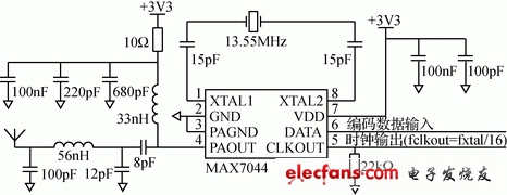
The transmission circuit diagram composed of MAX7044 is shown in Figure 2. According to the actual impedance of the antenna and the input impedance of the RF transmission chip, the π-type matching network is used to complete the impedance matching between the RF transmission chip and the antenna to achieve maximum power output.

Figure 2 MAX7044 circuit diagram
earphones headphones headsets
earphones headphones headsets
Shenzhen Linx Technology Co., Ltd. , https://www.linxheadphone.com
