Lei Fengnet Note: The author of this article is Dr. Gao Xiang. Simultaneous Localization and Mapping, instant positioning and map building technology. Whether it is indoors, outdoors, in the air, or underwater, the SLAM is the first problem encountered when a robot enters an unknown environment. This issue will introduce the basics of SLAM: sensor and visual SLAM framework.
Sensor and Vision SLAM Framework
In recent years, intelligent robot technology has been greatly developed in the world. People are committed to using robots in real situations: from mobile robots in the room, to autonomous driving vehicles in the field, drones in the air, and detection robots in underwater environments, etc., have received extensive attention.
In most cases, we will encounter a fundamental difficulty in the study of robots. That is positioning and construction, which is the so-called SLAM technology. Without accurate positioning and maps, the sweeping machine cannot move autonomously in the room and can only randomly touch; the home robot cannot reach the room exactly as instructed. In addition, in Virtual Reality and Augmented Reality (Argument Reality), users cannot roam in the scene without the positioning provided by SLAM. In these fields of application, people need the SLAM to provide spatial positioning information to the application layer, and use the SLAM map to complete the construction of the map or the generation of the scene.
sensor
When we talk about SLAM, the first thing to ask is the sensor. The implementation and difficulty of SLAM are closely related to the form and installation of sensors. The sensor is divided into two major categories: laser and vision , and the vision is divided into three directions. The following will take you to know the characteristics of each member of this huge family.
1. Sensor laser radar
Lidar is the oldest and most studied SLAM sensor. They provide distance information between the robot body and obstacles in the surrounding environment. Common laser radars, such as SICK, Velodyne, and our domestic rplidar, can be used for SLAM. The laser radar can measure the angle and distance of obstacles around the robot with high accuracy, so that SLAM, obstacle avoidance and other functions can be conveniently realized.
The mainstream 2D ​​laser sensor scans an in-plane obstacle, which is suitable for planar robots (such as sweepers, etc.) for positioning, and creates a 2D grid map. This kind of map is very useful in robot navigation, because most robots can't fly in the air or go up the steps, and are still limited to the ground. In the history of SLAM research, almost all of the early SLAM studies were performed using laser sensors, and most of them use filter methods such as Kalman filter and particle filter.
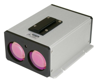
The advantages of the laser are its high accuracy, high speed, and low computational complexity, making it easy to implement real-time SLAM . The downside is that the price is expensive . If a laser is used for more than 10,000 yuan, it will greatly increase the cost of a robot. Therefore, laser research mainly focuses on how to reduce the cost of the sensor. The EKF-SLAM theory that corresponds to lasers is now very mature because of its earlier research. At the same time, people also have a clearer understanding of the shortcomings of the EKF-SLAM, such as the inability to express loopback, serious linearization errors, and the need to maintain the covariance matrix of the landmarks, resulting in a certain amount of space and time overhead, and so on.
2. The sensor's visual SLAM
Visual SLAM is one of the research hotspots of the 21st century SLAM. On the one hand, because the vision is very intuitive, one can't help but think: Why can't the robot recognize the way through the eyes? On the other hand, due to the increase in the processing speed of CPUs and GPUs, many visual algorithms that were previously considered impossible to implement in real time can be operated at speeds above 10 Hz. The improvement of hardware has also promoted the development of visual SLAM.
As far as sensors are concerned, visual SLAM research is mainly divided into three categories: monocular, binocular (or multi-view), and RGBD . There are special cameras such as fisheyes and panoramic views, but they are both rare in research and products. In addition, visual SLAM combined with Inertial Measurement Unit (IMU) is also one of the hotspots. In terms of difficulty of implementation, we can roughly sort these three methods as: Monocular Vision> Binocular Vision> RGBD.
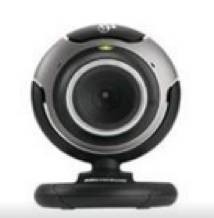
The monocular camera SLAM, referred to as MonoSLAM, can accomplish SLAM with only one camera. The advantage of this is that the sensor is particularly simple and the cost is very low, so the monocular SLAM is very much concerned by researchers. Compared with other visual sensors, the biggest problem with monoculars is that they can't get depth exactly. This is a double-edged sword.
On the one hand, due to the unknown absolute depth, monocular SLAM can not get the robot trajectory and the real size of the map . Intuitively, if you double the trajectory and the room at the same time, the monoculars see the same thing. Therefore, the monocular SLAM can only estimate a relative depth, which is solved in the similar transformation space Sim(3) instead of the traditional Euclidean space SE(3). If we have to solve in SE (3), we need to use some external means, such as GPS, IMU and other sensors to determine the scale of the trajectory and map.
On the other hand, monocular cameras cannot rely on an image to obtain the relative distance of the object from the image. In order to estimate this relative depth, monocular SLAM rely on triangulation in motion to solve the camera motion and estimate the spatial position of the pixel. That is to say, its trajectory and map can only converge after the camera moves. If the camera does not exercise, it cannot know the position of the pixel. At the same time, the camera motion cannot be a pure rotation, which brings trouble to the application of the monocular SLAM. Fortunately, when the SLAM is used everyday, the camera will rotate and translate. However, there is also an advantage to being unable to determine the depth: it makes the monocular SLAM not affected by the size of the environment, so it can be used both indoors and outdoors.
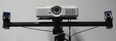
Compared to monoculars, binocular cameras estimate the location of spatial points by using a baseline between multiple cameras. Unlike monoculars, stereo vision can be estimated both during exercise and at rest, eliminating many of the troubles of monocular vision. However, the binocular or multi-camera camera configuration and calibration are more complex, and its depth range is also limited by the dual-purpose baseline and resolution. Calculating pixel distances from binocular images is a very computationally intensive task and is now done with FPGAs.
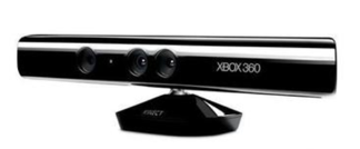
RGBD camera is a kind of camera that began to rise around 2010. Its biggest characteristic is that it can directly measure the distance of each pixel in the image from the camera through infrared structured light or Time-of-Flight principle . Therefore, it can provide richer information than traditional cameras, and it does not have to calculate depth as time-consuming and laborious as monocular or binocular. Currently used RGBD cameras include Kinect/Kinect V2, Xtion, etc. However, most RGBD cameras now have many problems such as narrow measurement range, large noise, and small visual field. Due to range limitations, it is mainly used for indoor SLAM.
Visual SLAM framework
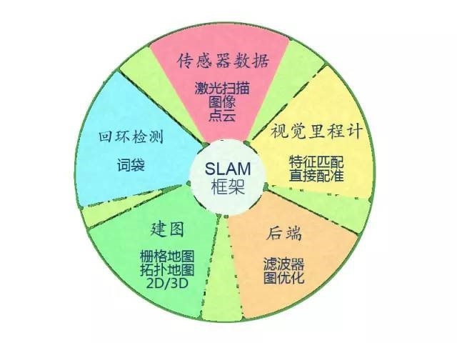
Visual SLAM has almost a basic framework. A SLAM system is divided into four modules (removing sensor data reads): VO, backend, map creation, loopback detection. Here we briefly introduce the meaning of each module, and then detail its use.
Visual odometer of SLAM frame
Visual Odometry, the visual odometer. It estimates the robot's relative movement (Ego-motion) at two moments. In the laser SLAM, we can match the current observation with the global map and solve the relative motion using ICP. For the camera, which moves in Euclidean space, we often need to estimate a three-dimensional transformation matrix - SE3 or Sim3 (monocular situation). Solving this matrix is ​​the core issue of VO, and the idea of ​​solving is divided into feature-based ideas and direct methods that do not use features.
Feature matching
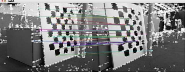
The feature-based approach is currently the mainstream of VO. For two images, the features in the image are first extracted, and then the camera's transformation matrix is ​​calculated based on the feature matching of the two images. The most commonly used are point features such as Harris corners, SIFT, SURF, ORB. If an RGBD camera is used, the motion of the camera can be directly estimated using feature points of known depth. Given a set of feature points and the pairing relationship between them, the pose of the camera is solved. This problem is called the Perspective-N-Point. PnP can be solved with nonlinear optimization to get the positional relationship between two frames.
The method of performing VO without using features is called direct method. It directly writes all the pixels in the image into a pose estimation equation and determines the relative motion between frames. For example, in an RGBD SLAM, a transformation matrix between two point clouds can be solved using an ICP (Iterative Closest Point). For monocular SLAM, we can match the pixels between two images or match the image to a global model. Typical examples of direct methods are SVO and LSD-SLAM. They used the direct method in monocular SLAM and achieved good results. At present, it seems that the direct method requires more calculations than the feature VO, and also has a higher requirement for the camera's image acquisition rate.
Behind the SLAM framework
After VO estimates inter-frame motion, the trajectory of the robot can theoretically be obtained. However, visual odometers, like ordinary odometers, have a problem of accumulated errors (Drift). Intuitively, at t1 and t2, the estimated corner is 1 degree less than the real corner, and then the trajectory will be less than 1 degree. Over time, the built room may have changed from a square to a polygon, and the estimated trajectory will have serious drift. So in SLAM, the relative motion between frames is also put into a process called back-end processing.
The early SLAM back-end uses a filter approach. Since the concepts of front-end and back-end haven't been formed at that time, people sometimes call the work of researching filters to study SLAM. The earliest proponents of SLAM, R. Smith et al., built the SLAM into an Extended Kalman Filter (EKF) problem. In accordance with the EKF format, they wrote the SLAM as a motion equation and observation method. To minimize noise items in the two equations, a typical filter idea was used to solve the SLAM problem.
When a frame arrives, we can measure the relative motion between the frame and the previous frame (via the code wheel or IMU), but there is noise, which is the equation of motion. At the same time, through the sensor's observation of the road signs, we measured the pose relationship between the robot and the road markings, and it also has noise, which is the observation equation. With these two information, we can predict the robot's position at the current moment. Similarly, we can calculate a Kalman gain based on the previously recorded landmarks to compensate for the effects of noise. Thus, the estimation of the current frame and landmarks is the continuous iteration of this prediction and update.
After the 21st century, SLAM researchers began to learn from the SfM (Structure from Motion) method and introduced Bundle Adjustment to SLAM. There are fundamental differences between the optimization method and the filter method. It is not an iterative process but considers information from all past frames. Through optimization, the error is divided equally into every observation. Bundle Adjustment in SLAM is often given as a graph, so researchers also call Graph Optimization. Graph optimization can intuitively represent optimization problems, can be solved quickly using sparse algebra, and it is also very convenient to express loopback. Therefore, it becomes the mainstream optimization method in visual SLAM.
SLAM Frame Loopback Detection
Loopback detection, also known as loop closure detection, refers to the robot's ability to recognize when it has reached the scene. If the test is successful, the cumulative error can be significantly reduced. Loopback detection is essentially an algorithm that detects the similarity of observed data. For visual SLAM, most systems use the now more mature Bag-of-Words (BoW) model. The bag-of-word model clusters the visual features (SIFT, SURF, etc.) in the image and then builds a dictionary to find what “words†each chart contains. There are also researchers using traditional pattern recognition methods to build loopback detection into a classification problem and train classifiers for classification.
The difficulty with loopback detection is that the wrong test results can make the map very bad. These errors fall into two categories: 1. False Positive, also known as Perceptual Aliasing, which means that different scenes are considered to be the same; 2. False Negatives, also known as perceptual variations (Perceptual Variability) refers to the fact that the same scene is treated as two. Perceptual deviations can seriously affect the results of the map and are usually intended to be avoided. A good loopback detection algorithm should be able to detect as many true loopbacks as possible. Researchers often use the accuracy-recall rate curve to evaluate the quality of a detection algorithm.
In the next period, we will specifically introduce these modules
Stay tuned!
Lei Fengwang Note: This article is authorized by the Daniel Bulletin Lei Feng network (search "Lei Feng network" public number concerned) release, if you need to reprint please contact the original author and indicate the author and source, may not delete the content. If you are interested, you can pay attention to the H.P. Horizon robotics technology and learn the latest news.
Alarm Cables
- Designed in a variety of structures from 12 AWG to 22 AWG , shielded type and unshielded type .
- Cables are available from 2 cores to 20 cores, stranded and solid, conductor can be bare copper or tinned copper.
- Support different applications and environments include security systems, alarm systems, power-limited control circuits systems,etc.
Alarm Cables,Cable For Fire Retardant,Cable For Fire Alarm Circuit,Alarm Security Cable
CHANGZHOU LESEN ELECTRONICS TECHNOLOGY CO.,LTD , https://www.china-lesencable.com
