one
Foreword
In recent years, the rapid development of Internet technology has affected all aspects of people’s lives and even changed people’s way of life. Compared to the vigorous development of Internet technology in recent years, short-wave communication technology is an ancient communication technology. Since 1901, Marconi, an Italian engineer, has achieved transatlantic radio communication and has experienced more than 100 years of development. Short-wave communication has the characteristics of low cost, short-wave communication equipment, strong portable type, long transmission distance, and no need for active relay, making it the main guarantee for communication in response to unexpected public events, natural disasters and other major emergencies. one. However, the communication quality of short-wave radio stations is directly affected by the electromagnetic environment of the area used and the erection method of the antenna. When the short-wave antenna is set in an area where the electromagnetic environment is good and there are no obstacles around, the short-wave communication quality will be significantly improved. Because of this, in order to obtain better short-wave communication quality, many emergency departments set up radios and antennas in open areas such as the mountains near command posts or on the roofs of high-rise buildings. The position of the command post cannot be set in the position of the shortwave radio station because of traffic or other reasons. Sometimes the position of the command post is located at a distance of 20km or more from the location where the short wave radio station is deployed. This needs to be passed at the command post. Some remote control devices remotely control short-wave radio stations erected on the nearby hills or high-rise buildings. The MK-302 speech data adaptive transmission module is a device developed for these needs with audio full-duplex real-time network transmission and data full-duplex real-time network transparent transmission functions, thereby realizing command post remote control systems and radio communication equipment. It is the real-time voice communication between short-wave radio stations and the remote-remote command control of short-wave radio stations, solving the real-time voice and data communication problems of ground-level short-wave radio stations by underground command posts.
two
Equipment introduction
The MK-302 voice data adaptive transmission module is a device that adapts to long-distance voice and data transmission in real time. Supports long-distance full-duplex real-time network transmission of voice, RS232-based serial port data real-time network transmission, and CAN bus-based data real-time network transmission and real-time network transmission of levels. It can be used for real-time voice transmission of remote stations and remote transmission of real-time radio control commands by the command post. It can also be widely used in any scenarios requiring remote audio and data transmission in real time.
MK-302 speech data adaptive transparent transmission module hardware uses STM32F407 chip as the main chip, uses WM8978 audio chip for audio A/D and D/A conversion, LAN8720A network chip is used for network transmission, and TJA1040 CAN bus chip is used for CAN Bus data transmission and reception, MAX3232 chip for RS232 port level conversion. The hardware structure of the block diagram as shown below:
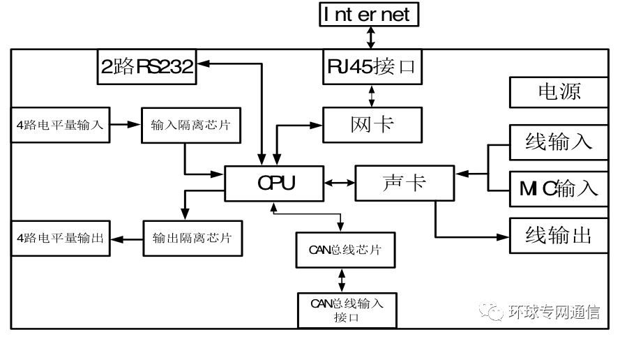
Figure 1 block diagram of speech data adaptive transmission module
The embedded software of the MK-302 speech data adaptive transparent transmission module is based on the UCOSII real-time operating system and developed with the LWIP network protocol stack. The MK-302 speech data adaptive transmission module also has the full-duplex network real-time transmission function of audio, serial data, CAN bus data and level, which requires that the operating system used can execute and schedule multiple tasks at the same time. The delay between each task should be as small as possible to ensure the real-time data transmission. The UCOSII real-time operating system satisfies the above requirements. The UCOSII real-time operating system has basic functions such as task scheduling, task management, time management, and memory management, and its small footprint and tailorable features are very suitable for embedded application operating systems. It is widely used for system development of various embedded chips. The LWIP protocol stack is used for the setup of TCP/IP networks and the network transmission of data. The LWIP protocol stack can run under the UCOSII real-time operating system environment. It supports the main functions of the TCP and UDP protocols, and the occupied microcontroller resources are relatively small. It is suitable for building a network transmission device based on a single-chip microcomputer.
The MK-302 voice data adaptive transmission module uses different network protocols for full-duplex real-time network transmission of voice and data. Full-duplex real-time network transmission of audio using UDP protocol without connection protocol. UDP protocol is not a reliable transmission layer communication protocol. In the case of a busy network or a poor network condition, the transmitted data packet may be lost, but the UDP protocol has the characteristics of small occupied resources and fast data processing. Audio data integrity requirements for the data is not very high, even if some data packets are lost, it will not have a greater impact on the results received, so the connectionless protocol UDP protocol is very suitable for audio network real-time transmission. The transparent transmission of data must ensure the integrity and reliability of the transmitted data. Therefore, transparent network transmission of data adopts a more secure and reliable TCP network protocol. According to the definition of RFC793, the TCP network protocol is a connection-oriented, reliable, byte-stream based transport layer communication protocol.
The MK-302 speech data adaptive transmission module can support two different network transmission modes: unicast and multicast, and can set two different audio input sources (MIC input or line input), audio The output gain is configurable and the audio transmission function is configurable. The MK-302 speech data adaptive transmission module can adapt to different application scenarios.
three
Application scenario
3.1 Point-to-point real-time audio and data network transmission (unicast)
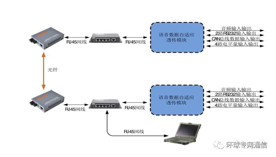
MK-302 voice data adaptive transmission module as shown above, can be point-to-point audio, data transmission, voice, RS232 data, CAN bus data and level data through the public network, private network or local area network IP network Full duplex network transmission. It can be widely used in any scenarios that require long-distance real-time transmission of audio and data. For example, an application scenario that requires remote monitoring of the device, an application scenario that requires long-distance real-time transmission of audio, or a device that requires real-time transmission of device control instructions has been implemented Remote control application scenarios.
The MK-302 speech data adaptive transparent transmission module uses the web server to configure various parameters of the module, and can easily view and modify the various parameters of the module. There is no need to install supporting software. Simply enter the IP address of the corresponding module in the address bar through the web browser that is connected to the same IP network of the module and enter the configuration page of each parameter of the module. In the parameter configuration page, you can view the current parameters of the module and edit and modify the parameters of the module.
3.2 Remote control and real-time voice transmission of short-wave radio stations (unicast)
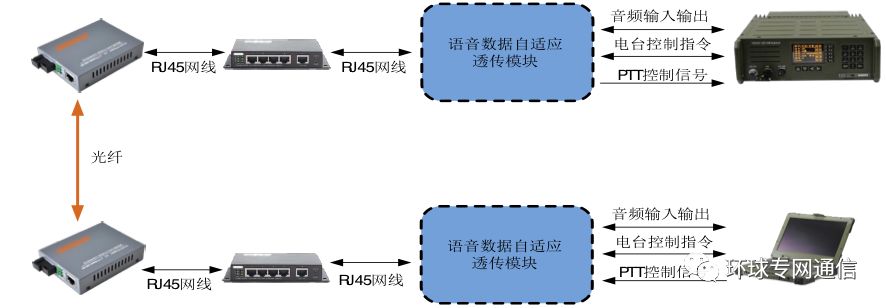
Based on the point-to-point audio data network transmission application scenario introduced in 3.1, the MK-302 speech data adaptive transmission module can be used by the command post to remotely control short-wave radio stations and real-time voice transmission. The command post can send radio control commands to the near-end module through the RS-232 port of the local MK-302 speech data adaptation transparent transmission module through a computer or other device. After receiving the radio control command, the near-end module receives the received commands. The radio control command splits the data according to the RS232 data transparent transmission protocol, and transmits the packaged radio control command through the network to the remote MK-302 voice data adaptive transmission module. The remote module is based on RS232. The transparent transmission protocol parses the radio control commands from the received network data packet and sends the radio control command to the radio through the RS232 port of the transparent transmission module to realize the remote control of the short wave radio.
The voice signal can also be digitalized through the audio input port of the near-end MK-302 speech data adaptive transmission module, and then transmitted to the remote MK-302 speech data adaptive transmission module through the network. The digital audio signal is decoded, and the decoded analog audio signal is sent to the shortwave radio through the audio output port to realize the remote transmission of the real-time speech signal.
The PTT level can be sent to the near-end module through the level input port of the near-end MK-302 speech data adaptive transmissive module, and the digital signal can be processed after the near-end module receives the level signal. , and digitally processed level signal is sent to the remote module through the network, the remote module parses the PTT level input signal of the near end according to the level transparent transmission protocol, and then passes the PTT level amount through the level The output port is sent to the connected shortwave radio.
The specific application of the short-wave radio remote control and real-time voice transmission is shown in the following figure:
3.3 Real-time audio signal multicast network transmission (multicast)
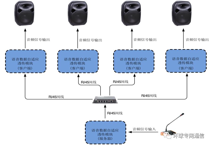
The MK-302 voice data adaptive transmission module can implement audio multicast simplex real-time network transmission. Connect three or more MK-302 speech data adaptively transparently transmitted modules in the same IP network environment, and set one of the MK-302 speech data adaptively transparent transmission modules to work in server mode. Other MK- The operation mode of the 302 speech data adaptive transmission module is set to the client mode, and all the multicast addresses and multicast ports of the MK-302 speech data adaptive transmission module connected in the same network environment are set to the same group. Broadcast addresses and multicast ports enable real-time multicast network transmission of audio signals. As shown in the figure below, when the working mode is that the server's MK-302 voice data adaptive transparent transmission module receives the voice signal, the received voice signal is digitized and transmitted through the multicast network transmission mode. To the remote client module that has the same multicast IP address and port as the server module, after the client module receives the audio data, the audio is played through decoding of the audio chip. This application scenario is very suitable for the formation of broadcast systems based on IP networks, such as schools or other public places. Compared to traditional broadcasting systems, broadcast systems based on IP network multicast can achieve the function of sending specific information to specific modules by adjusting the multicast IP address and port of each module. By connecting a computer or other device to the network to which the module belongs, you can simply and conveniently set up the multicast IP address and port or other parameters of all modules in the network through the built-in web browser.
four
Main functions and parameters
The main function of the MK-302 speech data adaptive transmission module is to achieve real-time transmission of audio data and real-time transparent transmission of data. The detailed function introduction and parameter description of the device can be found in the device function table and parameter description table below.
Table 1: Device function table
| Function item | Rack type | Instructions | |
| 1 | 12V power input | √ | √: Must be equipped with X: Not available ○: Optional |
| 2 | Power protection | √ | |
| 3 | Universal WEBSERVER configuration parameters | √ | |
| 4 | Local module IP address, TCP port, UDP port configurable | √ | |
| 5 | Remote module IP address, TCP port, UDP port configurable | √ | |
| 6 | RS232 serial data network real-time transmission (can be used for radio transmission function) | √ | |
| 7 | 2-way RS232 data input and output | √ | |
| 8 | 2-way RS232 parameters can be configured independently | √ | |
| 9 | CAN bus data network real-time transmission | √ | |
| 10 | CAN bus parameters can be configured | √ | |
| 11 | 4-way level input network real-time transmission | √ | |
| 12 | 4-way level output network real-time transmission | √ | |
| 13 | Full-duplex audio network real-time transmission | √ | |
| 14 | 2-channel audio input channel | √ | |
| 15 | 2-way audio input channel configurable | √ | |
| 16 | 1 channel audio output | √ | |
| 17 | Audio output gain adjustable | √ | |
| 18 | Module operating mode can be configured | √ | |
| 19 | Audio full duplex transmission configurable | √ | |
| 20 | Support multicast (one-way audio transmission) | √ | |
| twenty one | Multicast IP address and port configurable | √ |
Table 2: Equipment Parameter Description Table
| Numbering | Types of | range | Instructions |
| 1 | WEBSERVER configuration page address | Need to configure the module IP address | Enter the configuration page to configure the relevant parameters of the module |
| 2 | Local IPv4 address setting | Set the module local IPv4 address | This address is the module's own IPv4 address |
| 3 | Remote IPv4 address settings | Set the remote device's IPv4 address | This address is the IPv4 address of the remote device to which the module needs to connect (this parameter is used in unicast mode) |
| 4 | Local TCP, UDP port settings (this parameter is used for unicast work mode) | Set the module's local data and audio send and receive ports | This port is the data and audio sending and receiving port of the module itself. The recommended port number is greater than 10000. |
| 5 | Remote TCP, UDP port settings | Set data and audio send and receive ports for remote devices | This port is the data and audio sending and receiving port of the remote module that the module needs to connect to. The recommended port number is greater than 10000. (This parameter is used for unicast work mode) |
| 6 | Multicast IP address and port settings | Set the multicast IP address and port | Multicast IP address range (224.0.2.0-238.255.255.255) Recommended port number greater than 10000 (This parameter is used for multicast mode) |
| 7 | Module operating mode settings | Set module operating mode | Set the working mode of the local module (server or client) |
| 8 | Audio full duplex network transmission settings | Set whether to enable audio full duplex network transmission | If you only need data transmission without audio transmission, you can turn off audio full-duplex transmission and save bandwidth (only if the network transmission mode is unicast). |
| 9 | Network transmission mode settings | Set the network transmission mode to unicast or multicast | When the application scenario is one-to-many transmission (such as the school's voice announcement system), the network transmission mode can be set to multicast. In this case, the audio is simplex and does not support transparent transmission of data. When the application scenario is one-to-one transmission, the network transmission mode may be set to unicast. At this time, the audio is full-duplex, and data transmission is supported. (The network transmission mode can be set only after the audio transmission function is turned on) |
| 10 | Serial 1 parameter settings | Baud rate, stop bit, data bits, parity, cache size Parameter settings | Set the relevant parameters of serial port 1. In principle, the serial port parameters corresponding to the local and remote devices should be consistent. |
| 11 | Serial 2 parameter settings | Baud rate, stop bit, data bits, parity, cache size Parameter settings | Set the related parameters of serial port 2. In principle, the serial port parameters corresponding to the local and remote devices should be consistent. |
| 12 | CAN bus parameter settings | CAN bus baud rate setting | The CAN bus baud rate of the module can be set. In principle, the baud rate settings of the CAN bus between the local and remote devices should be consistent. |
| 13 | Audio input channel settings | Set the module's audio input channel | Set the audio input channel (MIC or line input) |
| 14 | Audio output gain setting | Set the module's audio output gain | Audio output gain range (0-100%) |
| 15 | reset | Recovery module parameters are factory settings (default setting) | Press the KEY 1 button in the upper left corner of the module circuit board for 10 seconds. Release the button when the module status light is on. After a period of time, when the module status light goes out, it indicates that the module is successfully restored to factory settings. This function can be used to make users forget the current parameter settings or cause the module to work unstable due to improper parameter settings |
3. Equipment main technical characteristics
| project | Technical indicators |
| Audio input channel number | 2-way (MIC or line input) |
| Input audio characteristics | 15mVrms~5Vrms@600Ω adaptive |
| Output audio characteristics | 10mVrms~300mVrms@600Ω adjustable |
| Audio delay time | Less than 40ms |
| Level input and output channels | 4 inputs, 4 outputs |
| Level input and output voltage | Maximum DC 80V |
| RS232 serial port channel | 2 |
| RS232 serial port baud rate | 38400bps maximum |
| CAN bus channel | 1 |
| CAN bus baud rate | 1Mbps maximum |
| Operating voltage range | DC12V |
| Total power consumption | 100mA@DC12V |
4 module size and interface layout
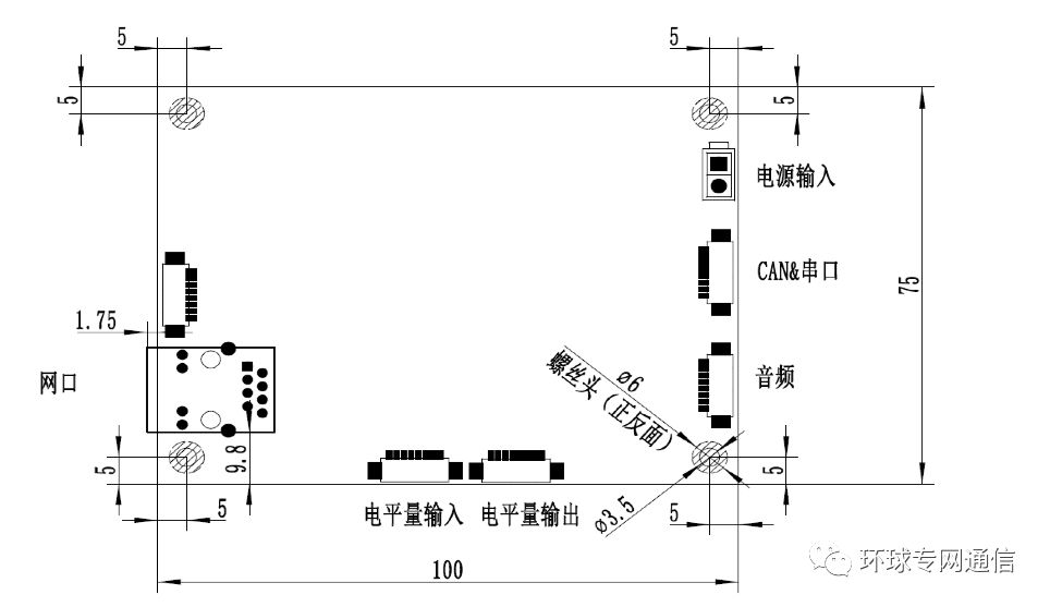
Kadena (KDA) is a hybrid blockchain network and smart contract platform that aims to unite public applications, private blockchains, and other interoperable chains in one place, driving traffic to the high-bandwidth computer at the heart of the Kadena public chain. Kadena`s mining algorithm is Blake2S, which supports ASIC mining.
Kadena is a blockchain network and smart contract token aiming to bring together both public applications and private blockchain.
The coin solves various problems that prevent blockchain adoption on a bigger scale. The protocol enables businesses and developers to make transactions and share information across many networks.
The Coin is actually on the grid to reduce users` experience in the network. Ethereum users experience a lot of network congestion which results in high gas fees.
A few changes have come into Kadena mining. A proof of work blockchain uses PACT to create smart contracts in the hidden gen. Therefore you need to know the following before mining Kadena. PACT is an intelligent contract language serving the needs of the blockchain community.
1.You Need an Excellent Mining Hardware
To mine efficiently, you will require suitable mining hardware. Kadena uses ASIC miners. But, unfortunately for Kadena miners, CPUs and GPUs are not usable. Furthermore, ASIC mining receives support from the Blake2S algorithm.
2.Make Sure You Have a Kadena Wallet Address
You will need a Kadena wallet address to receive and monitor your profit. F2pool also makes the distribution of the revenues to every user daily at 2KDA. The Kadena node wallet is a perfect wallet where you can receive your mined KDA. all you need to do is install it, click receive, and have a new wallet address.
You will need to configure your Asic Miner to a mining pool server for your hashrate and profit to be recorded and monitored.
3.Start Mining
After all the setting is done, your miner will be ready to work. Make sure you enter your wallet address and click on the go button to receive your revenue.
Kda Miner,Antminer Ka3 166Th,Bitmain Antminer Ka3 166Th,Antminer Bitmain Ka3
Shenzhen YLHM Technology Co., Ltd. , https://www.ylhm-tech.com
