For low-cost, low-power multi-output power supplies, the technical specifications often show that in order to maintain regulation, a minimum load must be applied to one or more of the outputs.
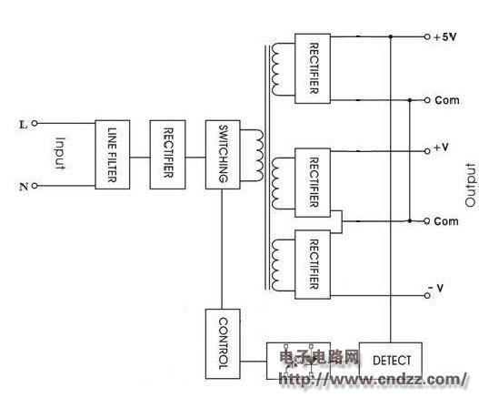
To explain why, the following provides a schematic diagram of the operation of a simple three-output power supply. 
Input——Input; Output——Output; Line filter——Input filter circuit; Rectifier——Rectifier circuit; Switching——Switch circuit; Control——Control circuit; Detect——Output detection
On the right side of the middle of the figure are the three output windings of the transformer.
At output 1 (+5V), the output of the transformer is rectified and filtered to provide a stable DC output. If the output voltage is not at the set voltage level, such as due to load changes, the power supply will automatically correct. The process to achieve this is to first detect the output voltage, compare it to the internal reference voltage, and then feed the signal back to the control circuit through the optocoupler. The control circuit will adjust the pulse width of the converter accordingly. The adjustment rate of this way output is usually 1% to 2%.
However, on outputs 2 and 3 (+V and -V), it can be found that there is no feedback to the control circuit. These outputs are called "semi-regulated" outputs. For example, if the load on output 2 increases, the output will decrease slightly, but no automatic correction is provided. This pressure drop is expressed in the specification as load regulation, typically 3% to 5%.
Regarding the lowest load, if the load on output 1 is small or completely unloaded, the output will remain at the set voltage, but the switching converter pulse width will become extremely small. The output voltage on outputs 2 and 3 is greatly reduced due to the extremely narrow pulse width, especially when the output load is full, the 12V output voltage may drop to 8V.
Conversely, if full load is applied to output 1, but outputs 2 and 3 do not apply any load, the voltage on 2 and 3 will rise, so that the 12V output may exceed 14V.
The effect of load changes on output 1 on the "semi-regulated" outputs 2 and 3 is referred to in many instances as the "cross-regulation" characteristic.
The manufacturer of the power supply specifies a minimum load requirement for Output 1 to alert the customer, typically 10%. You can also specify a minimum load on outputs 2 and 3 to further achieve better regulation specifications.
Operating without specifying a minimum load will usually not cause a power failure, but will put pressure on the user's equipment.
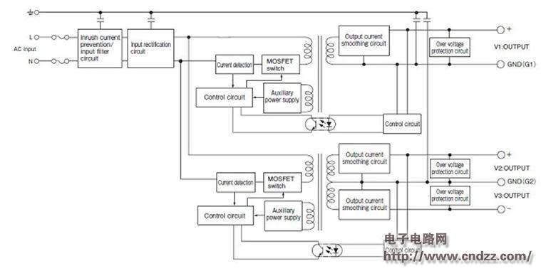
Some products, such as TDK-Lambda's MTW series, use two regulation circuits to improve the power supply's regulation specifications, one for powering output 1 and the other for output 2 and 3. Please note that both V2 and V3 are detected by the control circuit. 
AC input - AC input; Inrush current prevention / input filter circuit - Inrush current suppression / input filter circuit; Input rectification circuit - Input rectifier circuit; Current detection - Current detection; MOSFET switch - MOSFET switch; ——Control circuit; Auxiliary power supply——Auxiliary power supply; Output current smoothing circuit——Output current smoothing circuit; Over voltage protection circuit——Overvoltage protection circuit; GND (G1)——Ground (G1); V1: Output— —V1: ​​Output
Some products, such as the NV175 series, have a regulation regulator circuit on each output, completely eliminating the need for minimum load. Although it increases the cost of the power supply, it eliminates any user concerns and helps to achieve system flexibility.
Miniature Compression Force Sensor
Miniature Button Load Cells is a device that converts the magnitude of a force into an associated electrical signal. It also called Force Sensor,force transducer, small load cells are designed for compression and known for their small package size. They are used in tight and limited spaces. General purpose ones are normally designed with diaphragm construction but some higher precision ones are designed with bending beams for low capacity and shear or column design for higher capacity.
Miniature button load cells are available in various capacities ranging from 5N to 200KN and in packages ranging from 8mm to 51mm OD. (can customized the Load Cell size) , the force sensors are widely used in Medical applications as well as automation where small size is a must and space is limited. For detecting mechanical forces such as tension, tension, pressure, weight, torque, internal stress and strain. As industrial automation continues to increase, load cells will play an increasing role.
Force Sensor,force transducer,button load cell,Force washers sensor,miniature load cell
GALOCE (XI'AN) M&C TECHNOLOGY CO., LTD. , https://www.galoce-meas.com
