In today’s internal training, I recommend the key parameter design of EMI filter typical reference for household appliances; reference to the typical filter of FLY <75W with grounding system is as follows: (please explain in detail to Midea designers for reference)
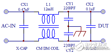
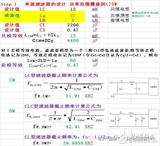
The equivalent design drawing of the typical differential mode common mode of the filter EMI-conduction is as follows:
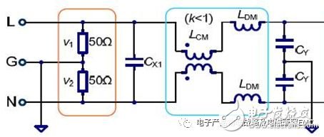
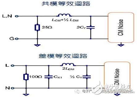
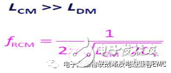
A. The fcn (resonant frequency)/cutoff frequency calculation formula of the equivalent circuit of the common mode as shown in the above figure is as follows:
B. The fcn (resonant frequency)/cutoff frequency calculation formula of the equivalent circuit of the differential mode as shown in the above figure is as follows:

CM/DM Noise Attenuation-The cut-off frequency of the filter is 10KHZ-50KHZ through practical data; its designed filter can be used in most applications! The theoretical calculation data of its parameters are as follows:
We determine the general method of fcn
The cut-off frequency fcn of the input filter of the switching power supply should be determined according to the electromagnetic compatibility design requirements. For the disturbance source, it is required to reduce the disturbance level to the specified range. For the receiver, the received value is reflected in the requirements for the noise limit. The cut-off frequency of the first-order low-pass filter can be determined by the following formula:
Harassment source: fcn=kT×(the lowest harassment frequency in the system);
Signal receiver: fcn=kR×(lowest disturbance frequency in electromagnetic environment);
In the formula, kT and kR are determined according to electromagnetic compatibility requirements, and generally take 1/3 or 1/5.
Examples are as follows:
A. The cut-off frequency of the power supply noise choke or power supply output filter is fcn=30~50kHz, and it is required to be lower than the maximum operating frequency of our switching power supply (when CLASS-A/B requires f=150KHz as the starting point of the test);
B. The cut-off frequency of the signal noise filter is fcn=10MHZ~30MHz (for information technology equipment with a transmission rate> 100Mbps).
In addition, for products and equipment with special waveforms of input current, such as power supply EMI input circuits connected with direct rectifier-capacitor filtering: electrical equipment and products such as switching power supplies and electronic ballasts without power factor correction (PFC), if To filter out the 2~27/40th (9KHZ) current harmonic conduction interference, the cut-off frequency fcn of the noise choke may be lower.
The description of other standard requirements is as follows:
The US Federal Communications Commission (FCC) stipulates that the starting frequency of electromagnetic interference is 300kHz;
The International Special Committee on Radio Interference (CISPR) specifies 150kHz;
The US military standard stipulates that it is 10kHz.
Design points: Insert filter design.
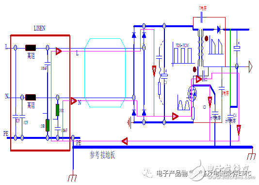
If the input filter is not inserted in the above figure, it is difficult for us to pass the EMI conduction limit requirements.
In actual application, if there is no low-pass filter inserted into the input EMI; we use differential mode and common mode separators to carry out the theoretical study of the filterless system as follows: The limits of the differential mode and common mode of our test are as follows:
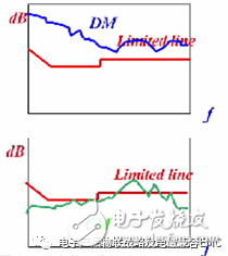
The actual test results we need to achieve are as follows: It is required to meet the test limits of CLASSA/B:
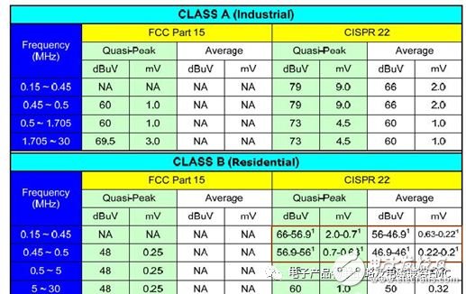
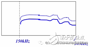
Usually the actual test is 5-10dB lower than the limit design! The actual value is the effect of the blue solid line, and the dotted line is our limit requirement.
We determine the exact theoretical method of fcn.
The cut-off frequency value of the filter is determined by the tangent division method according to the curve requirement.
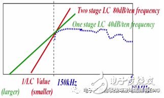
The cut-off frequency of the first-level low-pass filter can be determined as follows:
Harassment source: fcn=kT×(the lowest harassment frequency in the system); CLASSA/B=150KHZ-30MHZ (standard)
Receiver: fcn=kR×(lowest disturbance frequency in electromagnetic environment); CLASSA/B=150KHZ-30MHZ
In the formula, kT and kR are determined according to the electromagnetic compatibility requirements, and generally take 1/3 or 1/5; and are less than the design operating frequency of the switching power supply.
For the switching power supply design of FLY flyback <75W; the curve I obtained during the differential mode and common mode filterless separation test is performed when the attenuation curve obtained by the ClassB limit requirement is subjected to tangent analysis; the tangent point of fcn It happens to be almost 1/3 of 150KHZ; therefore, it is concluded that the cut-off frequency of FLY flyback switching power supply of <75W is around 50KHZ; therefore, my design suggests that the differential mode & common mode of FLY switching power supply <75W is cut The frequency is recommended to be designed at 10KHZ-50KHZ.
Therefore, it is recommended that my experimental parameters be iteratively designed for the filter design of the switching power supply <75W.
Please refer to: "Electromagnetic Compatibility Advanced Design and Optimization of Switching Power Supply System" Switching Power Supply-Conducted interference is the fastest method for efficient design.
My recommended design for the EMI filter whose system is a class II appliance/structure-products without grounding measures:
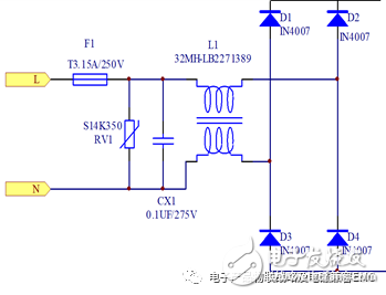
The principle calculation formula is the same as the calculation method of grounded Y capacitor design:
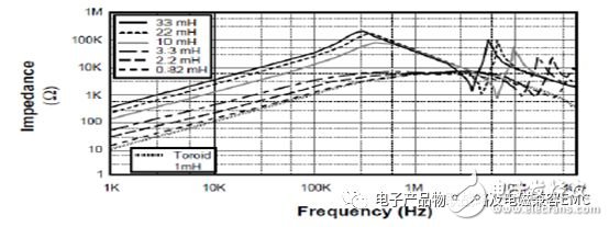
Note: In theory, the higher the inductance, the better the EMI suppression effect, but too high inductance will make the cut-off frequency lower, and the actual filter can only achieve a certain broadband, which will make the suppression effect of high-frequency noise worse. .
(Generally, the noise component of a switching power supply is about 1~10MHZ, but there are cases where it exceeds 10MHZ).
note:
The higher the inductance, the more winding turns and the higher the ferrite core ui, which will increase the low-frequency impedance (larger DCR). The increase in the number of turns increases the distributed capacitance, so that all high-frequency currents flow through this capacitance. Too high ui makes the iron core very easy to saturate. According to my many years of design experience, it is ideal for ferrite material ui=10K.
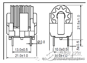
The above-mentioned EMI common-mode filter recommends FT20.6 or ET28; it is recommended to design the inductance at about 32mH if the partition/slot winding (Sectional Winding) is adopted, and the DS can be recommended to everyone if the specification is required.
High Quality Tablet Ram 4GB/8GB/16GB SODIMM UDIMM DDR4 8gb Laptop 2400mhz Ram
Model
DDR4 SODIMM
Brand
Semsotai /OEM /ODM /OBM
ECC
Non-ECC
Capacity
4GB/8GB/16GB
Chipsets
Samsung /SK Hynix/Mircon/Spec tek
Frequency
2133MHz/2400MHz/2666MHz/3200MHz
Speed
PC4-17000/PC4-19200/PC4-21300/PC4-25600
Componets Configuration
(256m/512m/1G) x8/x16
Memory CAS Lantency
CL15/CL17/CL19/CL21/CL22
Supply Voltage
1.2V
Pin Count
260PIN
PCB layer
8 /10 layer high speed PCB
Certificate
CE/FCC/ROHS
Operation temperature
0C-95C
Compability
100% Work with all motherboard
Ddr4 Laptop Memory,Ddr4 Rgb Ram,Ddr3 Ram 8Gb Pc 1600,Game Ddr3 8Gb
MICROBITS TECHNOLOGY LIMITED , https://www.hkmicrobits.com
